Jump to content
Banner by ~ Ice Princess Silky
  • entries
    10
  • comments
    99
  • views
    2,323

CRT... Old TVs and computer monitors. Scanlines. And more...


Splashee

1,723 views

The more time passes by, people get nostalgic about the past, about their childhood. Many PC gamers of the late 90s and early 2000 get very nostalgic when they see the CRT shaders applied to their favorite PC emulators. Many remember, but do they remember correctly?
 

(This applies to old consoles as well, such as Super Nintendo and Sega Genesis). A TV or computer monitor were made of a bulky heavy thing called a CRT. The thing that people remember the most are the scanlines, and that somehow, pixels were more smoother.
Then there are people who actually repairs CRTs today, and they know everything about how they work, in technical detail. That is cool and all.
But what about the general public, and this nostalgia factor?

This is a screenshot from DOOM, through a CRT:

doom-title-crt-lottes_mod-mycustom-shade

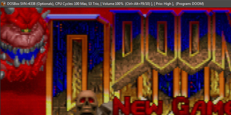
It's not through a real CRT. It is a PC emulator called DosBox and it uses a popular CRT shader called "lottes" with some custom settings dialed in to please the author of the screenshot.


What's wrong about this above image? Well, it is the scanlines. The shader takes the emulator screen and divides each pixel horizontal rows into scanlines. The scanlines are clearly taller to get the right aspect ratio for the game (probably not). You can see it at the top of the New Game graphics, that the red outline is only one scanline thick. If this was a real computer with a real CRT (where original DOOM was played on), there would be two scanlines instead of one.

Like we all remembered it?
Back when the first CRT shader showed up, around 2016, it did it right (with double scanlines, and aspect ratio, and all), and it got me very interested in getting myself the best possible real CRT monitor for my old PC, so that I could see the real thing, and remember the real thing.


Here are some (real) photos that I just took, from my Trinitron 21 inch CRT I bought in 2017, but it is from 1999:

single.jpg.1dba51caa748d26fd3bb1b2baba8ac73.jpg

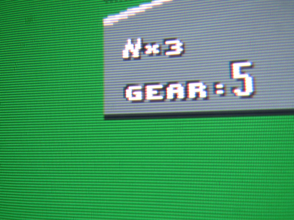
The "G" in GEAR's top scanline is one pixel height. This is because I am using a high resolution where pixels map to pixels. Thanks to Windows 98, I can do that. But the real thing is below...


dual.jpg.60df23c06081e5fbebc9cb7e59e3587b.jpg

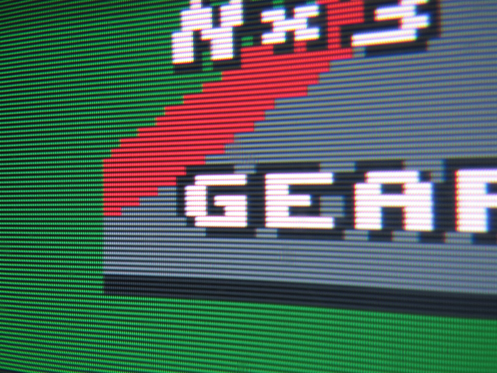
Now, this is how DOOM would display its art (I don't have DOOM to test on). The top of the G is now two scanlines. The art in the game is still only one pixel high! it is the CRT doing the thing here!

What is that green area on the left hand side?
This is what those emulators and shaders will never be able to fully understand. It is the border. It is outside the range of what can be drawn on. The pixels don't go there, but still, you see there is a border. A single color (green right now, but usually black and invisible), which stretches outside the area the game can draw on, but at the same time, doesn't fill up the entire CRT screen. It is a thing that most people just don't remember. I remember it. I love it.


Do you see all those little dots? Are they pixels? No, they are not pixels. (The technical name is "Shadow Mask"). With them, you get that smooth look that people sometimes associate with "real" pixel art. I am not here to say what is real or not. It is people's own preference how they want to view their art. Clean pixels. Scaled up pixels. Though a CRT. Anything is okay!
What is most common to remember about old TVs (CRTs) are the scanlines. You can clearly see the scanlines more than any horizontal division of pixels. It is quite easy to count how many pixels there are vertically, but almost impossible to exactly know how many pixels there are horizontally. A CRT is analog, meaning you can stretch the screen using dials usually on the CRT itself, so that it covers more/less area, but the screen doesn't look worse, and pixels don't seem to get uneven, because the CRT is analog, and the output is not digital like the monitor you use right now.

One last thing, and this is the shut down image from Windows 98, redrawn by me to show one single pixel:

one400.jpg.4e7596967e90392168e72f8f7d174458.jpg

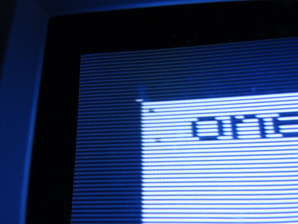
The white thing in the top-left corner is actually one square pixel in the art. The size of this art is 320x400 pixels. That is a huge vertical size compared to the horizontal size, but the CRT displays the image like if it was 4:3 aspect ratio, and it does it in a way that modern displays just can't do! That's because of the analog nature of a CRT. Now we are back to one pixel per scanline. This is the same screen mode as DOOM used, only hacked to show every scanline, instead of duplicating every scanline twice. DOOM ran in 320x200 (which stretches since that is not a 4:3 aspect ratio), and this mode above runs in 320x400, double the height. Both are displayed in 3:4 aspect ratio, making the pixel art look unique and not the same way it was originally drawn. Yes, game artists had to draw pixel art that would look stretched in the game, so they had to compensate. A round circle would become an ellipse if they just kept it exactly round in the original art.


The border in the above image is black. And because most borders are black, they are forgotten even by emulator authors (which are very wise people!). It saddens me that people don't think it is important just because it isn't currently visible.


If you were a game artist back in the day, you had to draw your art in a way so that it would be displayed correctly in these screen modes (not just computers, but Super Nintendo also had a resolution that was stretched. A Super Mario World sprite you can find online is probably not the same as it was intended to look) . Today, monitors display each pixel as square, and if they try to compensate, the result is blurry ugly pixels, or uneven pixels that break the illusion of the original art. CRT shaders do what they can to... at least get the aspect ratio back. But they do bring back a lot of nostalgia to people, and it is quite fun to see everyone's reaction online as they just think they went back in time, to a simpler, innocent time. A time when things were "better".


Spoiler

Linus from Linus Tech Tips goes crazy for a CRT sold for over $3000 from year 2002:


  • Brohoof 2

12 Comments


Recommended Comments

I miss old monitors and TV's. :worry:

Yes, the picture is clearer on new things but having black bars on older movies, TV shows and other programs drives me crazy! :mlp_okiedokieloki:

  • Brohoof 3
Link to comment

The scanlines as such only show up for monitors (or TVs) where the focus is very good (the beam is narrow) operating at lower resolutions. For example - using a monitor, capable of 1280x1024 at 640x480. Unlike a LCD (or Plasma), a CRT monitor can display different resolutions without scaling, but for it to be able to display high resolution, the beam with has to be small. If such monitor is used to display low resolution images, the "pixels" become bigger than the beam and you get this weird "scanline" look.

I can't see the scanlines on my monitor operating at 1920x1200. I can see them on a small TV, but only from up close (then again, the TV may need a focus adjustment).

  • Brohoof 1
Link to comment
48 minutes ago, Pentium100 said:

The scanlines as such only show up for monitors (or TVs) where the focus is very good (the beam is narrow) operating at lower resolutions. For example - using a monitor, capable of 1280x1024 at 640x480. Unlike a LCD (or Plasma), a CRT monitor can display different resolutions without scaling, but for it to be able to display high resolution, the beam with has to be small. If such monitor is used to display low resolution images, the "pixels" become bigger than the beam and you get this weird "scanline" look.

I can't see the scanlines on my monitor operating at 1920x1200. I can see them on a small TV, but only from up close (then again, the TV may need a focus adjustment).

Yes, high resolution on monitors really don't show much scanline, but the VGA modes such as the original VGA text mode that has the resolution 720x400 makes the scanlines somewhat visible on large monitors (17" and higher), and of course the EGA 640x350 text mode really shows the scanlines which AwardBIOS many times displayed with that Energy Star logo (there is a reason they used the EGA mode because 8x14 font instead of VGA's 9x16 where the 9th pixel would be duplicated of the 7th and ruin the logo).
Basically, scanlines are visible if the aspect ratio of the screen mode needs too much spacing between scanlines. It is possible to adjust the monitor's vertical height to view more scanlines, but not getting aspect results.


My Sony Trinitron TV is very blurry, aperture grille quite visible, and it doesn't show much at all of the scanlines for my Super Nintendo or Sega Saturn. Both consoles are running at 240p which is basically every even scanline on what would be 480i (interlaced). So technically, there should be a little bit of a scanline effect there, but I can't see it (clearly):

IMG_0053.JPG

IMG_0054.JPG


(these are actual photos from Sonic Jam (Sega Saturn with SCART) taken by me in 2011, so glad I still had them on my harddrive from 2004 rarity_shocked.png)

Link to comment
8 hours ago, Splashee said:

Basically, scanlines are visible if the aspect ratio of the screen mode needs too much spacing between scanlines.

It's not because of the aspect ratio, but resolution.

The beam width has to be as narrow as possible to get clear image at maximum resolution the monitor supports (bad focus = blurry image), if I need to adjust the focus on one of my monitors I use a strong magnifying glass to get it as possible. However, let's say you have a monitor that has screen size of 40cm x 30cm (50cm diagonal or 19.7") and supports maximum 1600x1200 resolution.

At the maximum resolution, you get 1200 lines in 30cm or 40 lines/cm). If you switch it to 640x480 (still 4:3 aspect ratio), you get 480 lines in 30cm or 16lines/cm. The lines have to be narrow enough so that 40 of them fit in 1cm, so when you have 16lines/cm, you have gaps between them.

8 hours ago, Splashee said:

My Sony Trinitron TV is very blurry

You should try adjusting the focus, but you have to be very careful doing it, since you can get zapped. Put some image with very narrow lines on the screen and adjust the focus potentiometer to get the most narrow lines. There may be other faults, but I would try focus first. 

But yeah, only displaying one field will result in gaps between scan lines.

  • Brohoof 1
Link to comment

@Pentium100 I'm definitely want to repair my CRTs at some point, to make them better. But I know the risk, and even with all the YouTube tutorials, I will still have to understand high voltage electricity a little better. I am quite good at working with 230VAC (by not working on it live) and low DC voltage, but when it comes to anything above that (even horse electric fence, or bug zappers), I am missing the actual understatement of "ground" and "grounded". Repairing CRTs have to wait.


So the beam width is staying the same no matter the resolution on real CRT monitors? It is what I thought, but the CRT shaders kinda don't care for that in PC emulation like Dosbox, and just scale scanlines to a percentage of the total resolution.

Link to comment
6 hours ago, Splashee said:

So the beam width is staying the same no matter the resolution on real CRT monitors?

Yes, the beam width is dependent on the tube itself and how well the focus is adjusted. I made some photos with a microscope

This is how it looks at 192x1200 (the only important number here is the second one):

http://www.pentium100.com/scr/1200.jpg

This is how it looks at 1280x800:

http://www.pentium100.com/scr/800.jpg

As you can see there are tiny gaps between the lines

And this is how it looks at 640x480:

http://www.pentium100.com/scr/480.jpg

Here gaps are larger and actually visible. Also, in this resolution, it looks like the convergence is a bit out (red, green and blue do not line up), but in practice it is impossible to see that, the difference is probably 0.05mm - 0.1mm and not possible to see without the microscope or a 10x magnifying glass.


7 hours ago, Splashee said:

I am quite good at working with 230VAC (by not working on it live)

Adjustments (sometimes diagnosing too) have to be done with the device on and usually warmed up. I have a big isolation transformer in case I need to, say, measure the hot side of a power supply with an oscilloscope etc.


11 hours ago, Splashee said:

I am missing the actual understatement of "ground" and "grounded"

Electric current can only flow in a circuit - it cannot go from point A to point B with no return path (unlike, say, a bullet). So, to get zapped by electricity, you have to touch two wires to form a circuit. 

Voltage is the potential difference, for example a 12V battery will have 12V difference between its positive and negative terminals. However, out of convenience, one of the points in the circuit is chosen as reference (which, by definition is at 0V potential) and all the voltages of the other points are referenced to it. 

Ground (the dirt outside) is conductive. It is sometimes used as the return path and you only need one wire for the power. Ground (dirt) is not as good conductor as a wire though, its resistance depends on the composition, how wet or dry it is etc, so for higher power lines actual neutral wires are used.

In theory, you can have a power line that is completely isolated from the ground. In practice it's not a good idea because the wires and dirt form a capacitor that can get charged to very high voltages (due to lightning strikes etc). To avoid this, the neutral wire is grounded at the substation. Yeah, there is a metal bar driven into the ground and neutral wire is connected to it.

So, basically, ground means the reference point or return path. 

How does it apply to safety. A battery is not connected to the ground and its voltage is only between its terminals. On the other hand, mains voltage is connected to the ground, so there is voltage between the live wire and anything else grounded (the ground outside, metal water pipes etc), so while you need to touch both terminals of the battery to maybe get zapped (if the voltage is high enough), you only need to touch the live wire, because you may be already touching something else grounded.

I mentioned an isolation transformer to work on power supplies - what it does is disconnect the device from ground, so now there is no voltage between any point of the device and ground, so it is 1) safer to touch with one hand and 2) safe to be measured with a grounded oscilloscope (otherwise I would just short out the supply trying to measure something or would need an expensive differential probe).

A good example is the electric fence - when you touch it, you form a circuit between the wire and dirt, so you get zapped. If you wear good rubber boots or stand on a plastic bucket, you won't get zapped.

As you can see, the people standing on insulators do not get zapped until the last one completes the circuit between the wire and ground.

This is for lower voltage (230V). For high voltage, say, the 20kV anode voltage in a TV (or spark plug wires), there is an additional challenge - at that voltage, not everything that appears to be an insulator actually is one. Such voltage can jump though a few mm of air and it can most definitely go through multiple layers of electrical tape, so you have to be even more careful because you may get zapped even if you touch the wire insulation instead of the bare wire. For example, a screwdriver with plastic handle is usually only rated for 1kV, so good enough for mains voltage, not good enough for 22kV.

On the other hand, the 22kV in a TV is only in the fat wire going from the flyback to the CRT. There is also the focus voltage (about 2kV) going to the neck board, but it is also somewhat contained. Everywhere else is 500V or lower. Don't touch those parts when the TV is on.

  • Brohoof 1
Link to comment
On 2022-05-28 at 5:18 AM, Pentium100 said:

completely isolated from the ground. In practice it's not a good idea because the wires and dirt form a capacitor that can get charged to very high voltages (due to lightning strikes etc)

That is a very good explanation of something basically every YouTuber out there that explains "ground" misses out on.


There is a horse fence not to far from where I live where someone has put a clip-on led light to blink when the high voltage spike happens. No one really says how such devices work, as there is no current going through, when the clip on doesn't put itself in series with the horse fence!


On 2022-05-28 at 5:18 AM, Pentium100 said:

Don't touch those parts when the TV is on.

Absolutely.

My confusion comes from people repairing CRTs, and removing that cup using a screwdriver. And the fact that many that also create tesla coils in their home (YouTubers) always say to find a ground to connect it to, and always uses Safety Ground (the green-yellow wire) in their closest found electric socket, which is like.... Hmmm?, is that what you use to lead the high voltage through? Does CRTs do that too? If it is a full circuit, how does the high voltage find it back to the source if it also travels through your circuit-breaker that detects ground faults and saves lives?

If I had a light bulb, and put one end of its socket to the live wire of any non-paid-for outdoor cable, and then just put the other end of its socket directly into the soil (ground), would I get free electricity (as well as being electrocuted of course), or would that blew a fuse to protect me because that is trying to drive something though "Safety Ground" (or joined PE, you know, 4 cord distribution line where Ground and Neutral share the 4th wire)?

These things are rarely talked about when YouTubers copy paste each other for electrician knowledge and subscribers. Gotta love that internet-copy-paste-knowledge-for-money.

Link to comment
52 minutes ago, Splashee said:

There is a horse fence not to far from where I live where someone has put a clip-on led light to blink when the high voltage spike happens. No one really says how such devices work, as there is no current going through, when the clip on doesn't put itself in series with the horse fence!

There are two ways this works.

1. Any time you see two conductors separated by an insulator - it's a capacitor. Some of them are very low value, but it is there. For example - any cable is also a capacitor. Most of the time the value is irrelevant, but sometimes it is actually important - for example, let's say there is a radio tuner or whatever that has a line level output, which has 100K output impedance. You connect it to an amplifier which has 1M input impedance and everything should be good, right? Well, at worst the level will be a bit lower. And it turns out that you get sound that lacks high frequencies, the reason being that the cable used has 200pF capacitance which forms a low pass filter with the output impedance of the source. So, a LED (or a neon bulb) connected at one end to a high voltage source can have enough current passing through it just because the other end forms a 0.1pF or whatever capacitor to ground.

2. Kind-of related to the first one, but sometimes you can just have very strong electromagnetic fields that would induce enough current in a LED or a fluorescent light to turn it on. You can see this happen under high voltage power lines or near a tesla coil.

This is also how a neon bulb based live tester works (the one that looks like a screwdriver). It has a neon bulb and a large value resistor in it, you stick it in an outlet and sometimes need to touch a piece of metal on the other end. Your body forms a capacitor with ground and there's just enough current (some microamps) to make the neon bulb glow. If the bulb glows you know it's live.


52 minutes ago, Splashee said:

My confusion comes from people repairing CRTs, and removing that cup using a screwdriver.

Net time look carefully and you should see the screwdriver connected by a wire to a ground wire on the outside of the CRT. This way, if there is high voltage present on the wire, it will be shorted to ground.

A CRT is a capacitor. Someone figured out that if you coat the outside of a CRT with some graphite coating (called aquadag, probably a brand name) and inside with conductive paint, you get a capacitor with the glass of the CRT acting as the insulator. This capacitor is used to smooth out the EHT and you don't need a separate high voltage capacitor for that. This means that even if the TV is off, there could be a charge there and there is some weird effect where if you discharge it and leave it unconnected, it can "charge itself" - probably because the glass was under high voltage for so long, some of the charge migrated inside it and takes a while to migrate back to the surface. Which is why if you disconnect the anode cap, leave the CRT shorted. A lot of the time you don't need to disconnect the anode cap though.

There is usually a wire (or multiple) attached to the outside of a CRT, usually with springs, this is the second connection of the capacitor. 

I remember one shango066 (good channel, he diagnoses and repairs various old TVs and radios and explains how the circuit should work etc instead of just recapping the TV or whatever) had some weird problem with a TV and it turned out that somebody painted the outside of the CRT with regular paint, instead of the conductive coating, meaning there was no capacitor and he had to connect a separate one.

52 minutes ago, Splashee said:

find a ground to connect it to, and always uses Safety Ground (the green-yellow wire) in their closest found electric socket, which is like.... Hmmm?

That's a bit wrong. Connecting one end of a CRT to the ground in in a power outlet doesn't do anything at best and makes it more dangerous at worst. Let's say I connect the anode pin to Safety Ground and the CRT develops a charge - well, now the entire outside of it is at some kilovolts with respect to ground - much easier to get zapped.

52 minutes ago, Splashee said:

If I had a light bulb, and put one end of its socket to the live wire of any non-paid-for outdoor cable, and then just put the other end of its socket directly into the soil (ground), would I get free electricity (as well as being electrocuted of course), or would that blew a fuse to protect me because that is trying to drive something though "Safety Ground" (or joined PE, you know, 4 cord distribution line where Ground and Neutral share the 4th wire)?

You would get free electricity and then a fine when someone sees you do that. Ground fault relays (they ave various names) are used in buildings. They work by measuring the current of both the phase and neutral (or all three phases and neutral), under normal circumstances, the currents should balance out. If they don't, it means the current is going somewhere else, for example though someone and into a water pipe. They work if you touch a live wire and something grounded, but if you grab live and neutral, then the relay will see it as "normal". Power lines do not have ground fault relays, at least I don't think so, it would mean lots of false positives that disconnect power for the entire neighborhood.

Edited by Pentium100
  • Brohoof 1
Link to comment

Awesome @Pentium100 as always! :eager:

I will check shango066 out and learn more about CRTs and high voltage as well. I had no idea the TVs acted as a capacitor that way (with paint). I know about capacitance in cables from the telephone stuff I do, and how the use of loading coils increased the inductance to help with longer transmission lines, a relic of the past, but still a fun one.


I might have remembered the whole tesla coil to safety ground wrongly because it was a long time ago that I watched it.

  • Brohoof 1
Link to comment
16 hours ago, Pentium100 said:

There are two ways this works.

1. Any time you see two conductors separated by an insulator - it's a capacitor. Some of them are very low value, but it is there. For example - any cable is also a capacitor. Most of the time the value is irrelevant, but sometimes it is actually important - for example, let's say there is a radio tuner or whatever that has a line level output, which has 100K output impedance. You connect it to an amplifier which has 1M input impedance and everything should be good, right? Well, at worst the level will be a bit lower. And it turns out that you get sound that lacks high frequencies, the reason being that the cable used has 200pF capacitance which forms a low pass filter with the output impedance of the source. So, a LED (or a neon bulb) connected at one end to a high voltage source can have enough current passing through it just because the other end forms a 0.1pF or whatever capacitor to ground.

2. Kind-of related to the first one, but sometimes you can just have very strong electromagnetic fields that would induce enough current in a LED or a fluorescent light to turn it on. You can see this happen under high voltage power lines or near a tesla coil.


From what I recall when we bought ours, its #2. I mean a fencer is usually, if I recall correctly, very high volts, very low amps, sent in bursts.

Those "fence sensors" are sensitive enough to detect static though, as I can drag my feet on carpet while holding one and it will light up in sync with me moving.

  • Brohoof 1
Link to comment
On 2022-05-30 at 11:22 AM, TheGleaner said:

I can drag my feet on carpet while holding one and it will light up in sync with me moving.

Yea, I almost forgot about that.

So, I have a horse fence at home to protect my pet ducks form foxes and other predictors, and it is reaching about 5 kV. Is there a way to build a little led indicator myself with just a red led and a very high resistor?

The opposite to this is the volt stick (brand name) that detects AC currents close to a wire and lights up a led. Those also activate if you rub them quickly against your clothes. I think they use an antenna and a darlington transistor (and battery to drive the led, which again is why I am questioning the led activating from variable range high voltage without breaking):
 

Spoiler


Link to comment

Create an account or sign in to comment

You need to be a member in order to leave a comment

Create an account

Sign up for a new account in our community. It's easy!

Join the herd!

Sign in

Already have an account? Sign in here.

Sign In Now
×
×
  • Create New...